Briggs & Stratton 8 User Manual
Browse online or download User Manual for Unknown Briggs & Stratton 8. Briggs & Stratton 8 User's Manual
- Page / 28
- Table of contents
- BOOKMARKS
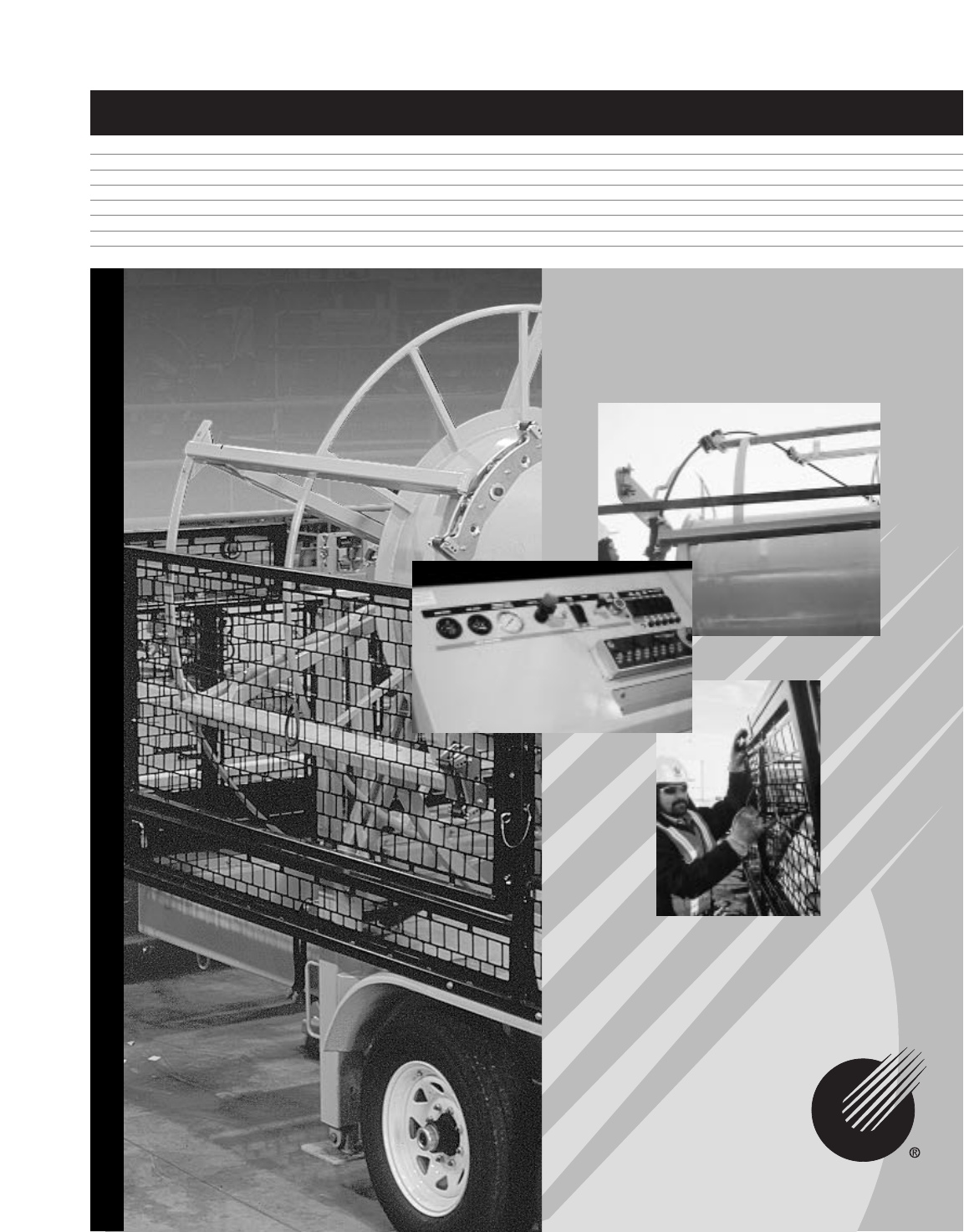
- Figure-8 Eliminator Trailer 1
- Important Safety Notice 2
- Table of Contents 3
- Technical Information 4
- OUT OF RANGE 5
- Safe Operating Practices 6
- Jobsite Set-Up Guidelines 7
- FUNCTION 11
- Prepare for Operation 12
- Load Cable 16
- Power Winding 20
- Unload Cable 22
- Prepare For Transport 23
- Troubleshooting Guide 24
- Service & Maintenance 24
- Parameter Settings 25
- Replacement Parts 26
- Warranty Information 27
- Condux International, Inc 28
Summary of Contents
Figure-8 Eliminator TrailerUSER'S GUIDE & SAFETY MANUALCONDUX
B. ELECTRONIC MACHINE CONTROLLERRefer to page 11 for a full explanation of the Electronic Machine Controller functions.C. FILTERS, GATE & EMERGENC
11Emergency StopSafety CagePressure FilterReturn FilterDrum CircuitArm CircuitBlower CircuitJack CircuitFUNCTION DESCRIPTION GREEN LED RED LED OFFGree
12Prepare for OperationIt is essential that the Figure-8 Eliminator Trailer be properly set up before operation. Using the following procedure will a
13D. Stabilize the trailer. Use only theadjustable leveling jacks (3 supplied) fortrailer stabilizing and leveling. Jacksmust be placed securely on
F. Move drum into load positionNOTE: Before starting the engine, check hydraulic fluid level, engine oil level,and diesel/gasoline fuel level.1. Hoo
15Figure 10. Electronic Machine Controller Panel15
166.Load CableTo begin the loading procedure the cable must be threaded and secured properlythrough the fairlead assembly, quad keeper rollers, double
17D. Rotate arms manually until the far rearward quad block is in a horizontalposition (Figure 14).E. Open rear fairlead assembly (Figure15) and lay c
18H. Close and lock the fairlead roller assembly (Figure 19).I. Proceed to next keeper roller on the arm. Continue to rotate arms manually and be su
19M. Manually spin arms around until the cable nests on the drum (Figure 23).N. Nest cable in notch on drum (Figure 24).O. Open cable clamp and secure
2Read and understand all procedures and safety instructions before using a Condux Figure-8 EliminatorTrailer. Observe all safety information on this
20Power WindingThe Condux Figure-8 Eliminator Trailer is capable of winding cable at an averagespeed of 600 ft/min (179 m/min) or about 40 RPM. This
21CAUTION! Side Tilt Panels must remain open and pinned, Access Doors mustremain closed during Power Winding operations. Be sure side panels aresecur
22I. Discontinue power winding when there are approximately 5 to 6 wraps of cable left on the cable spool. The last 5 to 6 wraps should beremoved fro
23F. Use the Drag dial to adjust the amount of drag placed on the arms duringunloading. It is essential to keep cable from developing slack. Start w
24H.Turn off Machine and Hand-Held Wired Remote Controller.I. Disconnect electronics and stow controllers in bin below Electronic MachineController (F
25Parameter SettingsThese parameter settings are loaded into the controllers at the factory and should not need adjustment. Please contact the factor
26B.Replacement PartsPart Number Description1 02267200 Kit, Tail Light-Waterproof Low Profile2 02278509 Connector, Trailer 7-Way Blade3 02288776 Cord
27Warranty InformationA. FACTORY ASSISTANCECondux International can provide further advice regarding any problems with theinstallation, service, assem
28© Copyright 2000, Condux International, Inc.Printed in USALiterature Part Number: 08739999Revision Number: 1.0Condux International, Inc.P.O. Box 247
3Table of Contents1256798Technical Specifications . . . . . . . . . . . . . . . . . . . . . . . . . . . . . . . . . . . . . . . . . . . 4Safe Operatin
Technical InformationThe Condux Figure-8 Eliminator Trailer is designed to greatly reduce cable splicingand the need to manually “figure-eight” cable
5OUT OF RANGEOUT OF RANGE• Full DOT approved lighting package with reflective tape• Front tongue jack, rated for 7,000 lb capacity.• Target trailer we
6Safe Operating PracticesRead and understand all procedures and safety instructions before using the ConduxFigure-8 Eliminator Trailer. Observe all s
7Jobsite Set-Up GuidelinesTime spent planning your equipment’s placement (layout) at the job site will benefit both the operation of the equipment and
84.Electronic Control Features and OperationA. HAND-HELD WIRED REMOTE CONTROLLER Load Dial• Controls the speed of the rotating arms from 0 rpm to maxi
9Stop button• This button will stop all operations of the machine.• LED beside button is lit when none of the other functions are operating. Alsofunc
Related products and manuals for Unknown Briggs & Stratton 8
 (76 pages)

 (72 pages)
(24 pages)
(14 pages)
(72 pages)
(24 pages)
(14 pages)
© 2020, manymanuals.com. All rights reserved. | 0.072 s |
 Manymanuals.com
 Manymanuals.de
 Manymanuals.fr
 Manymanuals.it
 Manymanuals.pl
 Manymanuals.cz
 Manymanuals.es
 Manymanuals-pt.com
Comments to this Manuals